
Views: 0 Author: Site Editor Publish Time: 2026-08-19 Origin: Site


The transition from part design to physical production forces a critical, budget-defining choice between subtractive and additive manufacturing methodologies. Selecting the wrong manufacturing process leads to compromised mechanical integrity, severe production bottlenecks, or exponential cost overruns at scale. Engineers and product designers must evaluate their project requirements against the physical realities of each method on the shop floor. You cannot simply send a CAD file to a machine and expect optimal results without understanding the underlying mechanics of how that material is shaped or deposited. This objective, evidence-based breakdown details when to leverage subtractive methods versus additive processes. We evaluate these technologies across dimensional accuracy, material properties, volume scalability, and overall production efficiency to help you make informed manufacturing decisions.
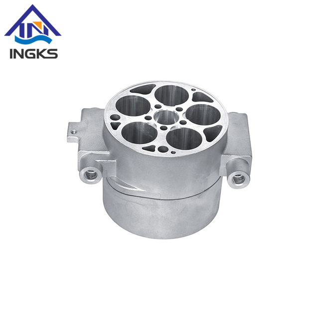
Fundamental Difference: CNC machining is a subtractive process that removes material from a solid block, ensuring superior structural integrity; 3D printing is an additive process building parts layer-by-layer, enabling unprecedented geometric freedom.
Precision and Performance: CNC machining remains the industry standard for tight tolerances, smooth surface finishes, and isotropic mechanical properties required in functional end-use parts.
Agility and Complexity: 3D printing excels in rapid prototyping, low-volume production, and manufacturing highly complex geometries (like internal channels or lattices) that are impossible to machine.
The Crossover Point: Unit costs for 3D printing remain relatively flat regardless of volume, whereas CNC machining becomes significantly more cost-effective at higher production volumes due to economies of scale offsetting initial setup costs.
Table of Contents
Understanding the core mechanics of these two technologies is the first step in successful part production. Subtractive manufacturing, which includes milling, turning, and drilling, starts with a solid block of raw material. Cutting tools systematically remove material until the final shape is achieved. The spindle drives the tool, and the machine axes move the workpiece or the toolhead to carve out the geometry. Additive manufacturing, encompassing technologies like Fused Deposition Modeling (FDM), Stereolithography (SLA), Selective Laser Sintering (SLS), and Direct Metal Laser Sintering (DMLS), builds parts by depositing or curing material one microscopic layer at a time. Instead of cutting away waste, the machine only places material where the cross-section of the part dictates.
Defining success criteria requires establishing baseline requirements for part evaluation. Engineers must analyze expected mechanical loads, operating environments, and lifecycle longevity. A component exposed to high shear forces or extreme temperatures demands different manufacturing considerations than a visual prototype used for ergonomic testing. You have to look at the yield strength, tensile strength, and thermal deflection temperatures required for the application. If a part is going into an engine bay, it needs to survive heat and vibration. If it is a custom surgical guide, it needs biocompatibility and precise anatomical conformity.
Industry compliance and standards heavily influence this decision. The aerospace, medical, and automotive sectors evaluate these processes rigorously for regulatory compliance. Material traceability, certification requirements, and predictable failure modes are non-negotiable in these fields. Subtractive methods have decades of established testing standards, while additive methods are rapidly developing their own certification frameworks for end-use applications. When you machine a part from a certified block of 7075-T6 aluminum, you have a mill test report guaranteeing its properties. Additive parts often require extensive coupon testing alongside the build to verify that the laser parameters and powder quality produced the expected mechanical baseline.
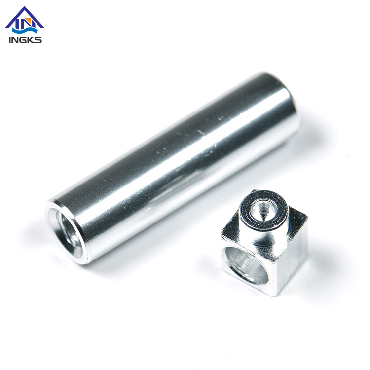
When functional requirements demand uncompromising precision, CNC Machining consistently delivers. Modern equipment routinely hits tight tolerances of ±0.001 inches or better. This dimensional accuracy directly impacts mating parts and complex assemblies, ensuring components fit together perfectly without manual rework. A machinist can dial in tool offsets to hit bearing fits or O-ring grooves with absolute repeatability. The rigidity of the machine tool, combined with high-quality cutting tools and proper workholding, eliminates the dimensional drift often seen in thermal-based additive processes.
Material selection and mechanical integrity represent significant advantages. Machining from extruded or cast billets results in isotropic properties, meaning the part exhibits uniform strength in all directions. Engineers have access to a vast library of engineering-grade metals and plastics. The grain structure of a rolled aluminum plate or a forged steel billet provides predictable, reliable performance under load.
Aluminum alloys (6061, 7075) for high strength-to-weight ratios.
Stainless steels (304, 316, 17-4) for corrosion resistance and durability.
Titanium (Grade 5) for aerospace and medical implants.
Engineering plastics (PEEK, Delrin, Nylon) for low friction and electrical insulation.
Brass and copper for electrical conductivity and thermal management.
The out-of-the-machine surface finish capabilities of subtractive processes are vastly superior to most additive methods. A well-programmed toolpath leaves a smooth surface that often requires no secondary finishing operations. This is critical for functional sealing surfaces, bearing fits, or high-end aesthetic requirements. By adjusting the feed rate and spindle speed, a machinist can achieve specific surface roughness averages (Ra). You do not have to deal with the stair-stepping effect inherent to layer-by-layer deposition.
Scalability follows a distinct curve. Subtractive manufacturing involves high initial Non-Recurring Engineering (NRE) costs. Programmers must generate CAM toolpaths, operators must design custom workholding fixtures, and machines require physical setup. However, these upfront investments amortize rapidly across medium-to-high volume production runs, making the per-part cost highly efficient at scale. Once the machine is set up and the first article is inspected, the cycle time per part is often measured in minutes or seconds. The machine can run continuously, sometimes lights-out with bar feeders or pallet pools, churning out thousands of identical components.
Additive manufacturing completely uncouples geometric complexity from production difficulty. Designers can implement lightweighting strategies, generate internal lattice structures, and consolidate multi-part assemblies into single printed components. Features like internal cooling channels, which are physically impossible to machine conventionally because a cutting tool cannot reach inside a curved cavity, are easily achieved layer by layer. This freedom allows for topology optimization, where software removes material from areas under low stress, resulting in organic, highly efficient shapes.
Rapid prototyping and iteration speed are the primary drivers for additive adoption. Moving from a CAD file to a physical part happens in hours. There is no need for custom tooling, complex CAM programming, or specialized workholding. This allows engineering teams to test multiple design iterations in the time it would take to set up a single subtractive run. You export an STL or 3MF file, run it through a slicer, and send it to the printer. If the prototype fails a fit check, you update the CAD, slice it again, and have a new version the next morning.
Despite these advantages, material limitations and anisotropy must be addressed. Many 3D printing methods exhibit inherent weakness in the Z-axis. Because parts are built layer by layer, the bond between layers is often weaker than the material itself, resulting in anisotropic mechanical properties. If you pull a printed part apart along the layer lines, it will fail at a lower force than if you pull it perpendicular to the layers. While the selection of production-grade additive materials is growing, it remains limited compared to traditional billet stock. You also have to account for thermal warping and shrinkage as the material cools from a molten state to a solid state.
Volume constraints prevent additive methods from competing economically and temporally with traditional manufacturing at high production volumes. The layer-by-layer deposition process is inherently slow. Printing ten thousand parts generally takes ten thousand times longer than printing one part, offering virtually no economies of scale. While print farms can increase throughput by running multiple machines in parallel, the cycle time per part remains static. You are fundamentally limited by how fast the print head can move or how fast the laser can scan across the powder bed without compromising part quality.
Contrasting the rigid precision of subtractive methods with the design flexibility of additive methods reveals distinct operational boundaries. Subtractive processes guarantee dimensional accuracy but restrict design to what a cutting tool can physically reach. You have to consider tool diameter, flute length, and the need for internal corner radii. Additive processes offer near-limitless geometric freedom but often sacrifice micro-level dimensional accuracy due to thermal shrinkage and layer resolution. You have to design for support structures, overhang angles, and thermal mass distribution.
Material waste and environmental impact differ drastically. Subtractive processes generate significant material waste in the form of swarf and chips. Machining a complex bracket from a solid block might result in 80% of the raw material being cut away. While metal chips can be recycled, the process is energy-intensive. Additive processes are highly efficient, using only the material necessary to build the part and its support structures. Powder bed systems can often recycle unsintered powder for future builds, minimizing raw material loss.
Evaluation Metric | Subtractive Manufacturing | Additive Manufacturing |
|---|---|---|
Setup Speed | Slow (Requires CAM, tooling, fixtures) | Fast (Direct from slicing software) |
Production Speed | Fast per part once running | Slow per part, constrained by volume |
Material Properties | Isotropic (Uniform strength) | Anisotropic (Weakness in Z-axis) |
Waste Generation | High (Chips and swarf) | Low (Highly efficient material usage) |
Geometric Freedom | Limited by tool access and workholding | High (Internal channels, lattices possible) |
Surface Finish | Excellent (Can achieve mirror finishes) | Poor to Moderate (Visible layer lines) |
The volume-to-time relationship dictates production schedules. 3D printing speed is fundamentally constrained by part volume. Larger parts scale print times exponentially as layer deposition accumulates. Conversely, subtractive speed is driven by material removal rates. Making large, simple parts is vastly faster to machine than to print. Additive wins on setup speed, getting the first part in hand quickly. Subtractive wins on raw material removal rates and per-part production speed once the machine is running. A high-speed machining center can hog out pounds of aluminum in minutes, whereas a printer might take days to build the same volume.
Post-processing requirements introduce hidden labor and time costs. Additive manufacturing often requires support removal, UV curing, thermal stress-relieving, and intensive surface smoothing to eliminate layer lines. Metal 3D printing requires cutting the part off the build plate with a wire EDM and running it through a furnace to relieve residual stresses. Subtractive manufacturing post-processing typically involves straightforward deburring, media blasting, or standard anodizing and coating procedures. The part comes off the machine much closer to its final state.
Mapping the economic trajectory reveals a clear cost-volume crossover point. Additive manufacturing is highly efficient for units 1 through 50. The lack of setup overhead makes it the logical choice for low volumes. However, as volumes reach the hundreds or thousands, subtractive methods become exponentially more efficient. The speed of production easily absorbs the initial setup investments. You have to calculate the break-even point based on the specific geometry and material. A simple blocky part will cross over to machining very quickly, while a highly complex manifold might remain cheaper to print even at higher volumes.
Tooling and setup costs highlight this divide. Additive processes require near-zero tooling investment. The printer bed is the universal fixture. You orient the part in the software, generate supports, and hit print. Subtractive processes require significant upfront investment for programming, custom workholding, specialized cutting tools, and machine calibration. You might need to machine custom soft jaws just to hold the part for the second operation. These NRE costs must be factored into the production run.
Modern facilities rarely choose just one technology; they utilize hybrid manufacturing strategies. Additive methods are deployed for rapid iteration, creating custom assembly jigs, and printing soft jaws for workholding. Subtractive methods are then utilized for final functional part production, ensuring the end product meets all mechanical and tolerance specifications. You might print a prototype to verify ergonomics, then machine the final production units from billet aluminum. You might also print a complex metal part near-net shape and then machine the critical mating surfaces to hit the required tolerances.
Transitioning between these technologies requires a fundamental design mindset shift. Design for Manufacturing (DFM) workflows differ entirely. Additive files, typically STLs or mesh formats, do not translate directly to subtractive toolpaths. Engineers must design for additive limitations, accounting for overhang angles, support contact points, and thermal shrinkage. You want to avoid large flat surfaces parallel to the build plate to minimize warping. Designing for subtractive limitations requires accounting for tool reach, internal corner fillets, minimum wall thickness, and realistic setup orientations. You have to ensure the cutting tool can actually reach the feature without colliding with the workpiece or the fixture.
Facility and infrastructure requirements present significant logistical hurdles. Desktop and industrial 3D printers generally operate within a quiet, office-friendly operational envelope. They need standard power and perhaps some basic ventilation. Subtractive equipment introduces significant noise, structural vibration, and safety hazards. Facilities require heavy power installations, dedicated ventilation, coolant and chip management systems, and safe material disposal protocols. You need reinforced concrete floors to handle the weight and vibration of a large milling center. You also need compressed air systems and proper lighting.
Operator expertise and labor costs further separate the two methodologies. Slicing software for additive manufacturing has a relatively accessible learning curve, allowing engineers to prepare builds with minimal training. The software automates much of the process, generating supports and toolpaths automatically. Subtractive manufacturing requires highly specialized, skilled labor. Generating efficient CAM programs, optimizing tool paths, calculating feeds and speeds, and safely setting up industrial equipment demands years of experience. A bad CAM program can crash a machine, destroying expensive spindles and tooling. Skilled machinists command higher labor rates because their expertise directly impacts part quality and machine safety.
Neither process is universally superior; the correct choice is dictated entirely by part geometry, required mechanical properties, and production volume. Additive methods dominate the prototyping phase and complex geometries, while subtractive methods remain the undisputed standard for precision, strength, and scalable production. Evaluate your specific project needs against the physical realities of the shop floor.
Wuxi Ingks Metal Parts provides precision CNC machining, custom metal component manufacturing, and engineering support for prototype and production projects. With advanced machining equipment, experienced technicians, and strict quality control, the company helps customers achieve accurate dimensions, reliable material performance, and consistent production quality.
Conduct a rigorous DFM audit of your current CAD files to identify features that dictate a specific manufacturing method.
Calculate projected annual part volumes to identify your specific cost-volume crossover point.
Consult with a dual-capability manufacturing partner to run a comparative analysis based on your exact material and tolerance requirements.
Implement hybrid workflows by using additive methods for internal tooling and fixturing to support your primary subtractive production lines.
A: It depends entirely on production volume. 3D printing is more cost-effective for single prototypes and very low volumes because it requires no tooling or setup. For medium to high volumes, machining becomes significantly cheaper per unit as the initial setup costs are amortized over a faster production run.
A: No. 3D printing uses slicing software to generate additive layer paths. Subtractive equipment requires specialized Computer-Aided Manufacturing (CAM) software to calculate tool speeds, feeds, entry angles, and material removal strategies based on specific cutting tools and raw material properties.
A: Subtractive processes involve high-horsepower spindles physically tearing metal or plastic away from a solid block. This generates extreme friction, vibration, and noise. It requires heavy-duty power supplies, rigid concrete foundations, and complex fluid management systems for cutting coolants.
A: Subtractive manufacturing provides a vastly superior surface finish directly out of the machine. Additive processes inherently leave visible layer lines that require manual sanding or chemical smoothing. Machining can achieve mirror-like finishes depending on the toolpath and cutting parameters.
A: While highly dependent on part geometry and material, the crossover point typically occurs between 50 and 200 units. Below this threshold, additive is faster and more efficient. Above it, the rapid per-part cycle times of subtractive methods easily offset the initial programming and setup time.
A: In additive manufacturing, larger parts take exponentially longer because the machine must deposit material across a massive volume layer by layer. In subtractive manufacturing, large parts with simple geometries can be produced very quickly, as large cutting tools can remove massive amounts of material rapidly.


