
Views: 0 Author: Site Editor Publish Time: 2026-08-19 Origin: Site


Selecting the wrong manufacturing method for metal components routinely results in compromised structural integrity, blown budgets, and extended time-to-market. Engineering and procurement teams must constantly balance geometric complexity, strict tolerance requirements, part size, and production volume constraints when sourcing custom parts. Making the correct process choice early in the design phase prevents costly downstream revisions and ensures the final product meets all functional requirements. This guide provides an evidence-based framework to evaluate sheet metal fabrication against CNC Machining, breaking down cost dynamics, design limitations, material yield, and scalability factors to ensure optimal manufacturing outcomes. By understanding the mechanical realities of each method, teams can align their designs with the most efficient production strategy.
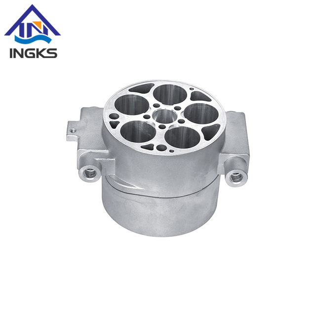
Precision vs. Form: CNC machining delivers superior accuracy and handles complex, solid 3D geometries, while sheet metal fabrication excels at producing lightweight, uniform-thickness components like enclosures and brackets.
Cost Scaling: Sheet metal fabrication generally offers lower per-part costs at high volumes due to faster cycle times, whereas CNC machining often presents lower upfront tooling costs but higher per-part costs for scaling.
Material Utilization: Subtractive CNC machining generates more material waste than formative sheet metal processes, directly impacting raw material expenditures.
Hybrid Solutions: Complex assemblies frequently require a strategic combination of both processes to balance structural rigidity, precision mating, and overall weight.
Table of Contents
This subtractive manufacturing process utilizes computer-controlled cutting tools to remove material from a solid block, known as a billet. Mills, lathes, and routers execute precise movements based on programmed instructions. The system relies entirely on G-code and CAM software for toolpath generation. Operators translate 3D CAD models into these machine-readable codes, dictating spindle speed, feed rate, and tool coordination. The spinning cutting tools shear away excess metal until the final geometric shape remains. This method allows for the creation of highly intricate solid parts from virtually any machinable material, offering unparalleled control over the final dimensions.
Modern machining centers operate on multiple axes, typically ranging from 3-axis to simultaneous 5-axis configurations. A 3-axis machine moves the cutting tool along the X, Y, and Z planes, which works well for relatively flat or straightforward parts. However, 5-axis machines can rotate the part or the tool head along two additional rotational axes. This capability allows the cutting tool to approach the workpiece from nearly any angle, enabling the production of complex undercuts, deep cavities, and organic contours without requiring the operator to manually reposition the billet. This continuous cutting process ensures high dimensional stability across the entire component.
Unlike subtractive methods, this approach combines cutting and formative processes applied to flat metal stock. Lasers, plasma torches, and waterjets cut 2D profiles from metal sheets with high speed and efficiency. Press brakes and stamping machines then bend, fold, and form these flat patterns into 3D shapes. The process heavily depends on the material's ability to undergo plastic deformation without fracturing. Operators must calculate bend allowances and deductions to ensure the final folded part matches the required dimensions. The initial flat pattern must account for how the metal stretches and compresses along the bend line.
Secondary assembly requirements often follow the initial forming stages. Technicians perform welding, riveting, and hardware insertion to create functional assemblies. Installing PEM nuts, standoffs, and captive screws directly into the sheet metal provides robust fastening points without the need for tapping thick blocks of metal. Spot welding and TIG welding join multiple folded panels together to form rigid enclosures or complex brackets. This multi-step workflow transforms raw, flat sheets into lightweight, structurally sound components optimized for specific spatial envelopes.
Subtractive methods excel at producing intricate internal features and multi-axis contours. Machining centers easily carve non-uniform thicknesses, deep pockets, and blind holes into solid metal. You can design parts with varying wall thicknesses to optimize strength-to-weight ratios in specific areas. For example, an aerospace bulkhead might feature thick mounting flanges connected by thin, webbed sections to reduce weight while maintaining structural integrity. The cutting tool can sculpt these varying thicknesses directly from a single piece of material, ensuring continuous grain structure and maximum strength.
Sheet metal faces strict limitations regarding uniform wall thicknesses. The entire part must maintain the thickness of the original flat sheet. Designers must also account for 2D-to-3D folding constraints. Bend radii and K-factors dictate how the metal stretches and compresses, restricting certain complex geometries. You cannot easily create a part with a 0.250" thick base and 0.060" thick walls using standard sheet metal processes. Every feature, from louvers to flanges, must be formed from the same uniform stock, requiring careful planning to ensure the flat pattern does not overlap or interfere with itself during the folding sequence.
Precision benchmarks separate these two manufacturing methods significantly. Machining centers routinely achieve tolerances between ±0.001" and ±0.005". This level of accuracy is mandatory for interlocking mechanical parts, bearing fits, and high-precision aerospace valves. When a shaft must press-fit into a housing, the dimensional variance must be tightly controlled to ensure proper function. Rigid machine frames, high-quality linear guides, and advanced thermal compensation systems allow modern mills and lathes to hold these tight tolerances consistently across production runs.
Sheet metal tolerances typically range from ±0.010" to ±0.030". Material springback after bending makes ultra-tight tolerances difficult to hold. When a press brake bends a piece of steel, the material naturally tries to return slightly to its original flat state once the pressure is released. Operators must over-bend the material to compensate, but variations in material hardness and thickness make exact predictions challenging. Thermal heat from cutting and welding also introduces warping. Bending mechanics inherently limit the precision achievable compared to rigid cutting tools.
Physical dimension requirements often dictate the primary process choice. Large-format enclosures, chassis, and structural panels are highly cost-prohibitive to carve out of giant metal billets. The machine time and raw material costs for such massive solid blocks make subtractive methods impractical for large, hollow structures. Removing 90% of a 500-pound aluminum block just to create a thin-walled box wastes an enormous amount of resources and ties up expensive machine time for days.
Sheet metal handles massive volumetric footprints efficiently. Manufacturers cut and fold flat sheets to create large panels and enclosures. This keeps shipping, handling, and material costs minimal while achieving the necessary structural footprint. A server rack or an industrial control cabinet relies entirely on folded sheet metal to provide a large internal volume without the excessive weight of solid metal. The ability to nest multiple large parts onto a single standard-sized sheet further optimizes material usage for these large-scale components.
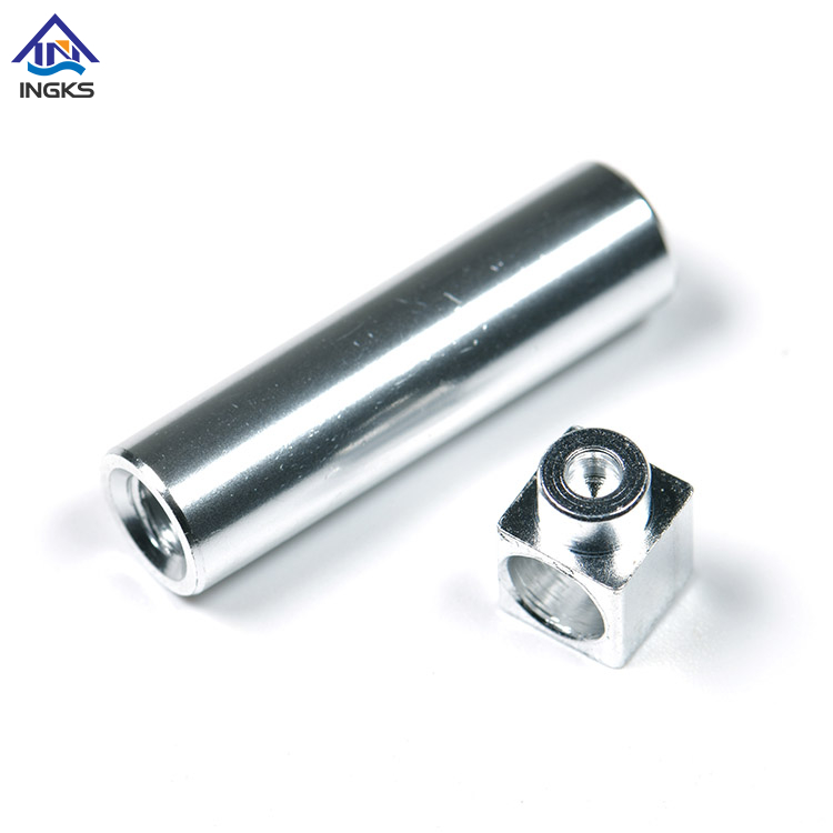
Setup costs differ drastically between the two methods. Machining requires extensive CAM programming and custom fixturing to hold the billet securely. The programmer must define every tool movement, select the appropriate cutters, and simulate the process to prevent crashes. Sheet metal demands flat-pattern generation and press brake setup. The operator selects the correct V-die and punch for the required bend radius and programs the backgauge positions. Both processes require upfront engineering time, but the nature of the setup dictates the most efficient production volumes.
During the custom prototyping phase, iterating CAD models impacts lead times. Programming a new machining toolpath is often faster than re-calculating sheet metal bend allowances and nesting layouts for a laser cutter. If a hole needs to move by 0.100", a CAM programmer simply updates the coordinate. In sheet metal, moving a hole might require adjusting the entire flat pattern to ensure it doesn't deform during a nearby bending operation. However, cycle times shift the advantage at scale. Sheet metal punching and laser cutting are exceptionally fast for high volumes. Machining cycle times remain relatively static per part, regardless of the total production volume.
Production Phase | CNC Machining Dynamics | Sheet Metal Dynamics |
|---|---|---|
Prototyping Speed | Fast toolpath updates, minimal physical tooling changes. | Requires flat pattern recalculation and potential die swaps. |
Setup Complexity | High (Custom workholding, extensive CAM programming). | Moderate (Standard dies, laser nesting software). |
High-Volume Cycle Time | Static (Cutting time remains constant per part). | Rapid (Punching and laser cutting scale efficiently). |
Design Iteration Cost | Low to Moderate (Software updates). | Moderate to High (May require new flat patterns). |
Material waste plays a significant role in overall expenditures. Subtractive manufacturing can result in 50% to 80% material loss as chips. You pay for the entire raw billet, even the material that ends up in the recycling bin. Sheet metal nesting software maximizes yield by packing flat patterns tightly onto the raw sheet, often achieving 80% to 90% material utilization. This difference in raw material efficiency becomes a major financial factor when scaling production to thousands of units.
Secondary operations also impact the final cost. Sheet metal assemblies often require welding, grinding, and finishing. A welded corner must be ground smooth to look aesthetically pleasing, which adds manual labor costs to the project. Machined parts frequently come off the machine ready for use or require only minimal deburring in a vibratory tumbler. Finally, high-volume machining requires frequent cutting tool replacement. End mills and drills wear down and break, and this tooling wear must factor into the long-term unit price calculations.
Machining centers handle a wide variety of solid materials. Ideal candidates include aluminum alloys like 6061 and 7075, which offer excellent machinability and high strength-to-weight ratios. Hard steels, stainless steel, titanium, and brass also perform exceptionally well, though they require different cutting strategies. Engineering plastics like Delrin, PEEK, and polycarbonate are common for non-metallic applications requiring tight tolerances and specific electrical or chemical properties.
Material hardness directly impacts machining time and tool wear. Harder materials like Inconel or hardened tool steel require slower feed rates, rigid setups, and specialized carbide or ceramic cutting tools. This increases production time and costs significantly. Softer alloys machine quickly but may require specific tooling geometries with high rake angles to prevent material smearing or built-up edge on the cutter. Understanding the machinability rating of a chosen material helps predict the actual production costs accurately.
Formative processes require materials that can bend without breaking. Ideal candidates include cold-rolled steel and stainless steel grades like 304 and 316. Aluminum alloys, particularly 5052, are highly popular due to their excellent formability and corrosion resistance. Copper is also frequently used for electrical busbars and grounding components due to its conductivity and ease of bending. The material must possess the right balance of strength and flexibility to survive the press brake.
Ductility, elongation yield, and tensile strength are critical properties. These factors prevent cracking during the bending process. Materials that are too brittle, such as 7075-T6 aluminum, will fracture along the bend line, rendering the part useless. Designers must match the bend radius to the material thickness and temper. A sharp bend on thick, hard material will almost certainly cause failure. Selecting a material with high elongation properties ensures the metal flows smoothly around the tooling during deformation.
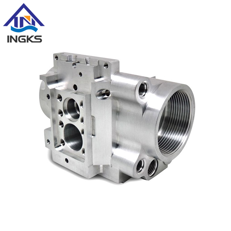
Designing for subtractive processes carries specific risks that can inflate costs and extend lead times. Engineers often design deep, inaccessible pockets that standard tools cannot reach. Specifying unnecessarily tight tolerances on non-critical features drives up costs needlessly by forcing the machinist to use slower finishing passes and perform rigorous inspections. Designing sharp internal corners requires specialized, expensive tooling like broaches or EDM processes, as spinning round end mills naturally leave a radius.
Standardize corner radii to match common end mill sizes, allowing the use of larger, more rigid tools.
Limit depth-to-diameter ratios for milled pockets to prevent tool deflection and chatter.
Apply tight tolerances only where functionally required for mating parts, leaving non-critical dimensions open.
Avoid designing features that require the part to be flipped or repositioned multiple times during machining.
Sheet metal design presents a different set of challenges. Specifying bend radii smaller than the material thickness causes cracking and weakens the structural integrity of the fold. Placing holes or features too close to bend lines results in distortion during forming, as the metal stretches and pulls the hole out of round. Ignoring material grain direction weakens the final part, as bending parallel to the grain increases the likelihood of fracturing.
Utilize standard tooling radii to avoid custom die charges and ensure consistent bending.
Adhere to minimum flange lengths recommended by the manufacturer to ensure the material sits securely on the V-die.
Always run flat-pattern simulations prior to production to verify bend allowances and prevent feature distortion.
Design relief cuts at the corners where multiple bends meet to prevent material tearing.
Raw material availability impacts project timelines. Billet stock for machining and flat sheet stock for fabrication may have different lead times depending on market conditions. Standard aluminum sheets might be readily available, while a specific diameter of titanium bar stock could require a multi-week lead time. Designing around standard material sizes and thicknesses helps mitigate supply chain delays and keeps projects on schedule.
Machine availability bottlenecks also affect delivery schedules. Advanced 5-axis machining centers often have longer queue times than standard 2D laser cutters due to their specialized nature and high demand. A shop might have ten laser cutters but only two 5-axis mills. Understanding the capacity of your chosen manufacturing partner helps set realistic lead time expectations and prevents supply chain disruptions. Diversifying your design to utilize more readily available processes can accelerate time-to-market.
Many complex assemblies require a strategic combination of both processes. Neither method is sufficient alone for certain applications. Relying strictly on one process often leads to compromised designs or inflated costs. By leveraging the strengths of both subtractive and formative manufacturing, engineering teams can create highly optimized products that meet strict performance criteria while remaining economically viable.
A common example is a sheet metal electronic enclosure. The main body utilizes folded sheet metal for lightweight protection and a large internal volume. Inside, machined aluminum heatsinks manage thermal loads from the electronics. Machined mounting standoffs ensure precise PCB alignment, which sheet metal alone cannot guarantee. Sourcing from a manufacturer equipped with both capabilities reduces vendor management overhead. This integrated approach balances structural rigidity, precision mating, and overall weight effectively, resulting in a superior final product.
The choice between sheet metal fabrication and subtractive machining depends entirely on specific project requirements. It is not about which process is objectively betterng high precision, complex 3D geometries, tight mating tolerances, and specific surface finishes. Choose formative sheet metal processes for lightweight enclosures, brackets, and panels where uniform thickness is acceptable, large envelopes are required, and high-volume scalability is needed.
Wuxi Ingks Metal Parts specializes in precision CNC machining, sheet metal fabrication, and custom metal component manufacturing for customers worldwide. Backed by advanced production capabilities and experienced engineering support, the company delivers high-quality prototype and production solutions tailored to diverse industrial applications.. You must align the manufacturing method with the geometric, tolerance, and volume constraints of the part.
Conduct a thorough DFM review of your current component designs to identify cost-saving opportunities.
Evaluate your production volume forecasts to determine the most cost-effective scaling strategy for your product lifecycle.
Upload your CAD files (STEP or IGES format) to a manufacturing partner for a technical consultation.
Request comparative quotes for both processes if your design allows for either manufacturing method.
A: It depends on the volume and geometry. Machining often has lower setup costs for prototypes but higher per-part costs at scale. Sheet metal has higher setup costs but becomes much cheaper per unit in high-volume production due to faster cycle times.
A: Yes. Machining centers frequently perform secondary operations on sheet metal components. This includes tapping precise threads, milling tight-tolerance pockets, or surfacing specific mating areas that standard punching or laser cutting cannot achieve.
A: Machining generally offers faster lead times for initial prototypes. Generating a toolpath from a 3D CAD model is often quicker than programming laser nests, calculating bend deductions, and setting up press brake tooling for a single sheet metal part.
A: Machining routinely achieves tight tolerances between ±0.001" and ±0.005". Sheet metal fabrication typically holds looser tolerances, generally ranging from ±0.010" to ±0.030", due to material springback and bending mechanics.
A: High volumes heavily favor sheet metal due to rapid punching and laser cutting speeds. Machining cycle times remain static per part, making it less cost-effective for scaling tens of thousands of units unless complex 3D geometry is strictly required.
A: Sheet metal fabrication is almost always better for electronic enclosures. It efficiently creates large, hollow, lightweight boxes with uniform walls. Machining an enclosure from a solid block wastes massive amounts of material and machine time.


