
Views: 0 Author: Site Editor Publish Time: 2026-10-23 Origin: Site


Correct indexing plunger installation helps maintain accurate positioning, smooth operation, and reliable component engagement. Incorrect mounting can cause binding, uneven wear, or loosening under vibration. Before installation, check the plunger dimensions, mounting method, receiving hole, and operating conditions.
This guide explains how to install threaded, smooth-body, and flange-mounted indexing plungers. It also covers alignment checks, fastening considerations, functional testing, and routine maintenance.
Table of Contents
Before mounting an indexing plunger, confirm that the selected model matches the application. Review the manufacturer's drawing and specifications before machining the fixture or preparing the mounting hole.
Check the following dimensions before installation:
Thread size or body diameter: Confirm that the mounting hole matches the plunger body.
Pin diameter and extension: Ensure that the locating pin can enter the receiving hole to the required depth.
Mounting depth: Check that the body does not interfere with nearby components.
Operating clearance: Leave enough room to pull, push, or rotate the handle.
Receiving hole dimensions: Follow the specified diameter, tolerance, and fit requirements.
Do not assume that one hole tolerance, such as H7, is suitable for every indexing plunger. The correct fit depends on the product design, pin dimensions, and application requirements.
Identify the forces acting on the locked assembly. Lateral loads can place shear stress on the pin, while axial forces may affect the joint depending on its design.
Compare the expected loads with the manufacturer's rated capacity. Consider load direction, engagement depth, repeated operation, and possible shock loads. Do not use the pin as the sole support for a load unless the component is designed and rated for that purpose.
Also check the operating environment. Moisture, dust, metal chips, chemicals, and high temperatures can affect the plunger body, spring, handle, or internal mechanism. Select a material and design suitable for the actual conditions.
Indexing plungers are available in different body and mounting designs. The installation procedure must match the selected model.
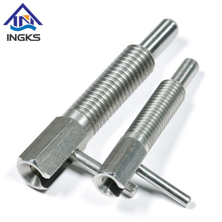
Threaded indexing plungers are installed in a compatible tapped hole. They are useful for fixtures and equipment that require adjustable positioning or convenient replacement.
Check the external threads and tapped hole for damage, burrs, and contamination.
Align the plunger with the mounting hole.
Start threading by hand to reduce the risk of cross-threading.
Turn the body into position according to the product drawing.
Tighten it using the manufacturer's specified method and torque, if provided.
Use a suitable locking method only when it is compatible with the product design.
Do not overtighten the body. Excessive tightening may damage the threads or deform the housing, potentially restricting pin movement. Avoid applying a generic torque value across different models and materials.
Smooth-body plungers use an unthreaded cylindrical body and require a compatible mounting arrangement. Depending on the design, the body may be installed in a prepared bore or retained by a specified mechanical feature.
Check the body diameter and required hole fit before installation. Use an appropriate press or fixture if the product requires a press fit. Apply force to the designated mounting surface rather than the pin or handle.
Do not assume that every smooth-body plunger can be welded, bonded, or retained in the same way. Use only the installation and retention method approved for the specific model. Unapproved welding or excessive heat may damage internal components.
Flange-mounted indexing plungers attach to a fixture surface through an integrated flange and mounting fasteners. This design can be useful when the base material is too thin to support a suitable threaded mounting hole.
Position the flange on the prepared mounting surface.
Align the plunger with the receiving hole.
Confirm that the mounting screws match the specified size and arrangement.
Tighten the fasteners according to the manufacturer's requirements.
Check that the flange sits securely and that the handle has enough operating clearance.
Confirm the flange dimensions and fastener locations before drilling the fixture. This helps avoid interference with adjacent components.
Inspect the plunger body, threads, pin, handle, and mounting hardware. Check for visible damage, burrs, corrosion, or contamination.
Clean the mounting and receiving holes before assembly. Remove chips and debris using a method suitable for the equipment and environment. Avoid leaving cleaning residue that could affect operation.
Machine or finish the receiving hole to the dimensions and tolerances specified for the application. A hole that is too small may restrict pin engagement. A hole that is too large may create excessive play or reduce positioning accuracy.
If the design requires a chamfer, make sure it is compatible with the pin geometry and does not prevent full engagement.
Alignment is essential for smooth pin movement. Misalignment between the plunger and receiving hole can increase friction, accelerate wear, or prevent the pin from engaging correctly.
Position the plunger and mating components according to the assembly drawing. Use suitable alignment tools or a fixture when needed. Secure the components before testing the pin movement.
For repeated indexing applications, consider a compatible receiving bushing where the design permits. A bushing can provide a replaceable contact surface and help protect a softer fixture material from wear. Confirm the bushing dimensions and fit before use.
Install the plunger according to its mounting design. For threaded models, start the threads by hand and stop if you feel unexpected resistance. Remove the component and inspect the threads rather than forcing it into position.
Use the specified tightening method and torque when the manufacturer provides them. Do not substitute values from a different model or use excessive force to compensate for a poor fit.
For applications exposed to vibration, check whether the product design permits a jam nut, compatible threadlocker, or another retention method. Follow the manufacturer's instructions, especially where later adjustment or replacement is required.
After installation, operate the handle manually. Retract the pin and release it. Check that the movement is smooth and that the spring returns the pin to its intended position.
For a locking model, test the locking and release functions according to its operating design. Do not assume that every model uses the same pull-and-turn sequence.
Check that the pin enters the receiving hole fully and does not catch on its edge. Confirm that the handle can move without hitting surrounding components.
Finally, verify the assembly under appropriate operating conditions. Keep personnel clear of moving parts and do not expose the joint to loads beyond its rated capacity. If the pin binds, fails to return, or does not engage fully, stop and identify the cause before putting the equipment into service.
A plunger may bind if its body and receiving hole are not aligned or if the hole dimensions do not meet the specified requirements. Burrs, debris, and damage can also interfere with movement.
Check alignment, clean the holes, and verify the dimensions before changing the plunger. Do not force a pin into a misaligned hole.
Vibration may cause a threaded component to loosen if its mounting arrangement does not provide adequate retention. Inspect the installation periodically and confirm that the plunger remains at the intended depth.
Where permitted, use the retention method specified for the application. A jam nut or compatible threadlocker may be suitable, but neither should be treated as a universal solution.
Dust, metal chips, moisture, and chemicals may interfere with the spring or pin mechanism. Select a plunger suitable for the environment and keep the mounting area clean.
Use protective measures only when they do not obstruct handle movement or interfere with the product's design. Inspect the component for corrosion, unusual friction, and changes in return action.
Establish an inspection schedule based on operating frequency, environmental conditions, and the consequences of failure.
During inspection:
Check the pin for visible wear, deformation, or corrosion.
Operate the handle and verify smooth movement.
Confirm that the spring returns the pin as intended.
Inspect mounting threads and retention hardware for loosening.
Clean away accumulated debris using an appropriate method.
Replace damaged or malfunctioning components before returning the equipment to service.
For high-cycle applications, use the manufacturer's inspection guidance where available. Do not rely on visual inspection alone if the application requires formal functional or load testing.
Correct indexing plunger installation starts with the right component, accurate hole preparation, and alignment with the receiving feature. Secure the plunger using the method specified for its design, then verify full engagement and smooth operation before use.
For different body styles and operating requirements, review the INGKS indexing plunger product range to compare available designs. Confirm dimensions, materials, and installation requirements against the specific product drawing before finalizing your fixture.
The required tolerance depends on the plunger design, pin diameter, and application. Follow the manufacturer's drawing instead of assuming that H7 is suitable for every model.
Use the retention method specified for the product and operating environment. A jam nut or compatible threadlocker may be suitable for some threaded models when permitted by the manufacturer.
Common causes include misalignment, incorrect hole dimensions, burrs, contamination, or excessive tightening. Check these factors before forcing the pin or changing the component.
Only if the specific product is designed for that installation method. Heat may damage the spring, handle, or internal components, so confirm the manufacturer's instructions first.
Inspection frequency depends on operating cycles, environmental conditions, and application risk. Check pin wear, handle movement, spring return, corrosion, and mounting security at suitable intervals.


