
Views: 0 Author: Site Editor Publish Time: 2026-10-12 Origin: Site


Choosing the correct grip length is essential when specifying a ball lock pin for a mechanical joint. The pin must accommodate the joined material thickness and allow its locking mechanism to engage as designed.
A pin that is too short may not lock correctly. An unsuitable grip length can also create unwanted movement or interfere with nearby components. These issues can lead to assembly problems, additional wear, and unplanned maintenance.
This guide explains how to define grip length, calculate joint thickness, account for tolerances, and compare fixed and adjustable ball lock pins.
Table of Contents
Confirm the dimensional reference: Use the manufacturer's drawing to identify how grip length is defined for the specific pin.
Measure the complete joint: Include all plates, brackets, and other components the pin must pass through.
Account for tolerances: Evaluate the expected range of joint thickness, including relevant coatings and manufacturing variations.
Verify locking engagement: Ensure the locking elements can reach their intended position after insertion.
Check the complete application: Consider handle clearance, joint geometry, load requirements, and the manufacturer's specifications.
Grip length describes the usable joint thickness that a ball lock pin is designed to accommodate. It is a key dimension when choosing a pin for plates, brackets, fixtures, or other connected components.
However, grip length should not be confused with overall pin length. Overall length may include the handle, shank, locking elements, and insertion tip. Grip length follows the dimensional references specified by the manufacturer.
Always check the drawing for the exact model before measuring or ordering a replacement.
Explore INGKS Quick Release Pins to compare available pin configurations and identify a suitable product for your application.
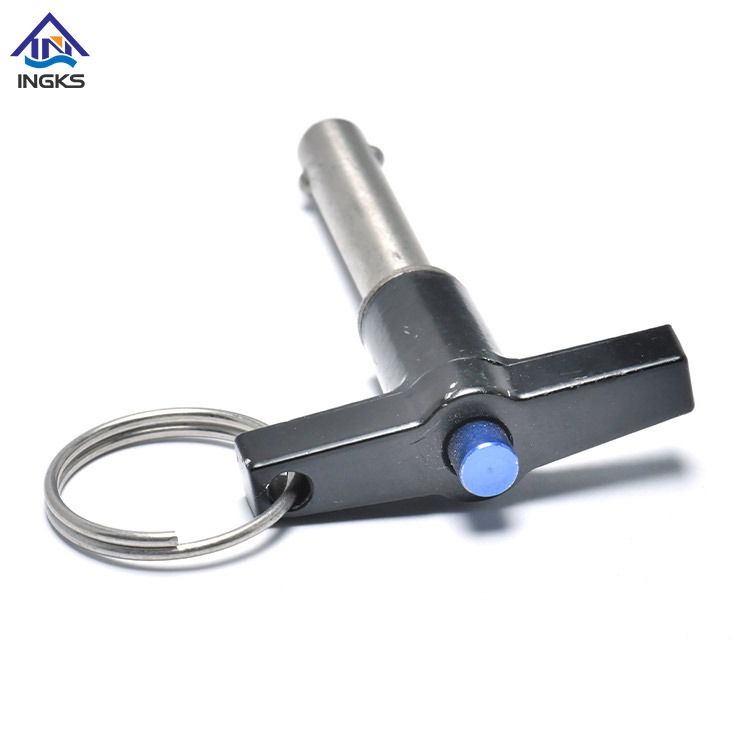
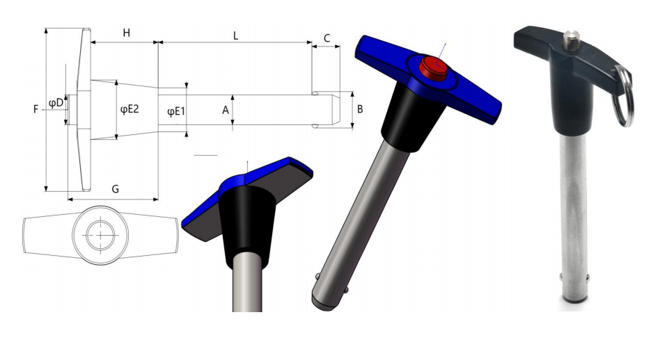
Before taking measurements, locate the grip-length dimension on the manufacturer's drawing. Identify the specified reference surfaces and confirm which part of the pin corresponds to the usable joint thickness.
Do not assume every ball lock pin uses identical measurement points. Designs may differ in handle geometry, shoulder configuration, and locking mechanism.
When checking an existing pin:
Identify the product model or obtain its dimensional drawing.
Locate the grip-length dimension and its reference points.
Measure the pin using the drawing's specified references.
Compare the result with the nominal dimension and manufacturing tolerance.
Avoid relying only on a visual estimate or the overall end-to-end length.
Measure all components that the pin must pass through. These may include plates, brackets, mounting tabs, and other parts in the joint.
For a simple assembly, the nominal joint thickness can be calculated as:
Nominal joint thickness = Sum of the nominal thicknesses of all joined components
For example, consider a joint with two steel plates:
Plate A: 0.500 inches
Plate B: 0.250 inches
The nominal combined thickness is:
0.500 + 0.250 = 0.750 inches
This value is a starting point, not necessarily the final grip-length specification. Actual component thicknesses, coatings, and manufacturing tolerances may change the total.
Measure the assembled components where practical. If the pin must fit multiple production assemblies, calculate the expected minimum and maximum joint thickness.
A joint's actual thickness may differ from its nominal CAD dimensions. Sheet material tolerances, machining variations, paint, powder coating, and plating can affect the final fit.
For a worst-case maximum-thickness check, add the maximum permitted thickness of each relevant component and any coating that increases the assembled thickness.
Assume the joint includes the following dimensions:
Component | Nominal thickness | Positive tolerance |
|---|---|---|
Plate A | 0.500 in | +0.015 in |
Plate B | 0.250 in | +0.010 in |
Coating allowance across the joint | — | +0.010 in |
The maximum estimated joint thickness is:
Plate A: 0.500 + 0.015 = 0.515 in
Plate B: 0.250 + 0.010 = 0.260 in
Coating allowance: 0.010 in
Maximum estimated joint thickness = 0.515 + 0.260 + 0.010 = 0.785 inches
This example assumes the coating allowance represents the total increase across the relevant mating surfaces. In an actual design, calculate coating thickness according to the surfaces coated and how they contact each other.
For assemblies with several toleranced components, a worst-case tolerance stack-up can help establish the maximum thickness the pin must accommodate. Where appropriate, engineers may use a different statistical method based on the design requirements.
Once the joint thickness range is known, compare it with the grip-length options and dimensional specifications for the selected pin.
Do not add a universal clearance margin to every application. The required relationship between grip length and joint thickness depends on the manufacturer's design, locking mechanism, joint geometry, and operating requirements.
Use this selection process:
Determine the nominal, minimum, and maximum joint thickness where relevant.
Check the manufacturer's definition and tolerance for grip length.
Confirm that the locking elements can engage in the intended position after insertion.
Verify that the handle or shoulder can seat correctly against the assembly.
Check the pin's tip clearance and the surrounding components.
Confirm that the selected model meets the application's load and retention requirements.
A longer pin is not automatically a better choice. Excess length may create unwanted movement or interfere with adjacent parts. The final selection must match the specified grip range and the actual joint geometry.
Correct grip length is only one part of a reliable pin connection. The locking elements must engage as intended, and the pin must suit the joint's load path.
The locking elements may remain within the joint instead of reaching their intended locking position. This can prevent correct engagement and allow unintended removal.
Before approving the pin, confirm that the locking elements clear the relevant mating surface as required by the product design.
Excess length may allow unwanted movement or create interference with nearby components. The effect depends on the joint geometry and the location of the locking elements.
Also inspect the relationship between the joint's shear planes and the pin's load-bearing section. Do not assume that every pin has the same internal geometry or that every tip has the same strength characteristics.
For load-bearing applications, check the manufacturer's ratings and verify the joint design. Pin diameter alone cannot establish the safe working load. Material, heat treatment, pin construction, shear-plane arrangement, bending, and fatigue may also affect performance.
Fixed and adjustable designs serve different application needs. The correct option depends on the required grip range, adjustment frequency, structural design, and available product specifications.
Selection factor | Fixed-grip pin | Adjustable pin |
|---|---|---|
Grip setting | Defined by the manufactured dimension | Can be adjusted within the design's specified range |
Typical application | Joints with predictable thicknesses | Applications that require a change in effective grip |
Setup | Select the correct catalog dimension | Set and verify the adjustment according to the instructions |
Load verification | Check the rating for the selected model | Check the rating at the applicable adjustment setting |
Purchasing | Standard catalog options may simplify sourcing | Confirm available adjustment range and model lead time |
Do not assume that fixed pins are always stronger or that adjustable pins always have longer lead times. Compare the actual product designs, load ratings, available dimensions, and delivery requirements.
For a fixed-grip option, review the INGKS Ring Button Handle Quick Release Ball Lock Pin. Check its drawing and specifications before matching it to a particular joint.
A pin may have the correct grip length but still fail to seat properly if the handle contacts a nearby wall, bracket, or recessed surface.
Check the handle's dimensions and operating envelope. Make sure the handle can reach its intended seated position and that the release mechanism remains accessible.
Temperature can change the dimensions of the pin and the joined components. The amount and direction of the change depend on the materials, geometry, and operating temperature.
For applications exposed to significant temperature changes, assess the expected dimensional variation and verify that the pin can still engage and release correctly.
Dust, mud, ice, corrosion, and other contaminants can affect pin insertion and locking operation. Increasing grip length alone does not guarantee reliable operation in dirty environments.
Consider material selection, protective measures, cleaning access, and maintenance requirements. Validate the pin under representative operating conditions when contamination could affect locking.
Always confirm the units used on the pin drawing and the assembly drawing. Converting between metric and imperial units can introduce rounding errors, particularly when selecting a standard catalog dimension.
Perform calculations consistently in one unit system. Convert only when needed, and verify the final selection against the manufacturer's actual dimensions and tolerances.
Mistake | Potential result | Recommended action |
|---|---|---|
Using overall length instead of grip length | Incorrect fit or incomplete locking engagement | Use the model-specific drawing |
Ignoring manufacturing tolerances | The pin may not accommodate all production assemblies | Calculate the relevant thickness range |
Applying a universal clearance margin | The selected grip length may not suit the design | Follow the product specifications and joint requirements |
Ignoring handle interference | The shoulder may not seat correctly | Check the surrounding operating space |
Selecting by diameter alone | Load or retention requirements may not be met | Verify the pin rating and complete joint design |
Mixing metric and imperial dimensions | The selected size may be unsuitable | Confirm units and actual dimensions before ordering |
Choosing the correct ball lock pin grip length starts with measuring the complete joint and confirming the manufacturer's dimensional references.
Account for component tolerances and relevant coatings, then compare the resulting thickness range with the grip-length options for the selected model. Check locking engagement, handle clearance, shear-plane position, and the manufacturer's load ratings before approving the design.
For procurement and engineering teams, a clear specification should include the required grip length, pin diameter, material, locking style, dimensional tolerances, and operating conditions.
Explore INGKS Quick Release Pins to review available configurations. For a specific application, provide the assembly drawing and operating requirements so the suitable pin dimensions can be verified.
Use the grip-length reference points defined in the manufacturer's drawing. Do not assume that overall length or a generic handle-to-ball measurement applies to every design.
Measure the combined thickness of all joined components, account for relevant coatings and manufacturing tolerances, and compare the result with the manufacturer's grip-length specifications and locking requirements.
No. A longer pin may create unwanted movement or interfere with nearby components. Verify the selected model's grip range, locking engagement, and joint geometry before choosing a standard size.
The locking elements may not clear the joint sufficiently to engage as designed. Confirm the grip-length reference and the position of the locking elements against the product drawing.
A fixed pin may suit a joint with a predictable thickness. An adjustable design may be useful when the required grip range changes. Compare the actual adjustment range, load rating, and operating requirements of the available models.


