
Views: 0 Author: Site Editor Publish Time: 2026-10-08 Origin: Site


Choosing the right quick release pin requires more than measuring its overall length. The shank diameter, grip length, receiving-hole size, and locking mechanism all affect fit and function.
Incorrect dimensions can cause installation problems, excessive movement, or incomplete locking. For engineers, maintenance teams, and purchasing professionals, understanding these measurements helps identify a suitable replacement and communicate specifications clearly.
This guide explains how to measure a quick release pin, check hole compatibility, and verify key selection requirements before ordering.
Table of Contents
Measure the shank diameter: Use calibrated calipers or a micrometer on the smooth cylindrical section.
Confirm the grip length: Follow the measurement reference defined in the manufacturer's drawing. Do not substitute overall length.
Check the receiving hole: Determine the required fit from the pin tolerance, hole tolerance, and application.
Allow space for the handle and locking elements: Verify that the pin can be inserted, locked, and removed without interference.
Verify load requirements: Diameter alone does not establish the safe working load of a pin assembly.
A quick release pin typically consists of a handle, a shank, and a locking mechanism. Each feature serves a different purpose and affects how the pin fits into an assembly.
Handle: Provides the interface for inserting, operating, and removing the pin.
Shank: The cylindrical section that passes through the aligned holes and transfers load between connected components.
Locking mechanism: Depending on the design, this may use spring-loaded balls or another locking feature to resist unintended removal.
Overall length, shank length, and grip length are different dimensions. Always check the manufacturer's drawing to identify the correct measurement references.
Explore Quick Release Pins to compare available pin styles and identify a product that matches your application.
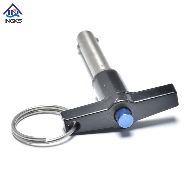
The shank diameter is a key dimension for determining whether a pin can fit through the receiving holes. It also affects the pin's load-bearing capability.
Use calibrated digital calipers or a micrometer.
Position the measuring faces across the smooth cylindrical section of the shank.
Avoid the insertion chamfer, locking balls, and visibly worn areas.
Take readings at more than one position when practical.
Compare the results with the manufacturer's nominal diameter and tolerance.
Do not automatically round a measured value to the nearest standard size and use that result as the purchase specification. Wear, measurement error, and manufacturing tolerances can affect the reading.
For example, a measured diameter close to 6 mm does not by itself confirm that every 6 mm pin is suitable. Check the actual part specification and the receiving-hole dimensions before choosing a replacement.
Grip length indicates the usable thickness of the joined components that a pin is designed to accommodate. The correct reference points depend on the pin design and the manufacturer's dimensional convention.
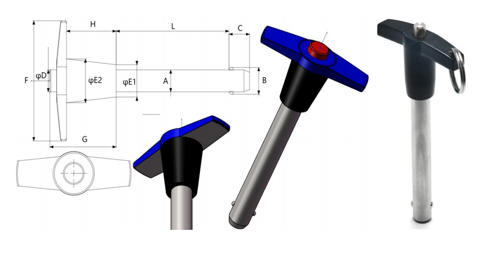
Find the grip-length dimension on the manufacturer's drawing.
Identify the specified reference points, such as the underside of the handle or shoulder and the designated locking-feature reference.
Measure the combined thickness of the components being joined.
Confirm that the pin can pass through the stack and that the locking elements can engage in their intended position.
Check the manufacturer's recommended grip range before ordering.
Do not assume that the full shaft length is available for gripping. The insertion tip, chamfer, and locking features may affect how the pin engages with the assembly.
A grip length that is too short may prevent proper engagement. A grip length that is unsuitable for the joint may also allow unwanted movement or prevent the handle from seating correctly. Confirm the required fit using the pin drawing and the actual assembly.
The receiving hole must accommodate the pin while meeting the application's positioning and movement requirements.
A quick release pin generally needs to be inserted and removed as intended by its design. However, the correct clearance is not a universal fixed value. It depends on the pin's actual diameter and tolerance, the hole tolerance, the materials, and the purpose of the joint.
Application | What to check |
|---|---|
General fastening | Confirm reliable insertion, locking, and acceptable movement in the assembled joint. |
Precision locating | Check the specified pin and hole tolerances and the required positional accuracy. |
High-load connection | Verify the design requirements, hole condition, pin rating, and load path. |
Outdoor or dirty environments | Consider contamination, corrosion, wear, and the need for inspection or maintenance. |
Do not apply one clearance value to every quick release pin. Use the manufacturer's specifications or the engineering drawing to establish the required fit.
Drilling alone may not achieve the required diameter, roundness, or surface finish for a precision locating application. Depending on the drawing and machining process, a hole may require reaming or another finishing operation.
The machining sequence and finishing allowance should be selected for the material, target tolerance, and available tooling. Inspect the finished hole rather than relying only on the nominal drill-bit size.
For a ball-lock design, the locking balls must be able to move into their intended locking position after insertion. The assembly must provide enough space for the locking features to engage without obstruction.
Check the following:
The pin can pass through all aligned holes.
The locking elements can engage as intended.
The exit side has enough space for the locking features.
The insertion tip does not bottom out prematurely in a blind hole.
Nearby components do not block the pin's insertion or removal.
Do not assume that every quick release pin uses the same ball geometry or locking method. Use the drawing for the exact model and verify engagement during fit testing.
A pin can have the correct shank diameter and grip length but still be unsuitable if its handle interferes with nearby parts.
Measure the handle's maximum width and height. Also consider the space needed to operate the release mechanism and remove the pin.
T-handles: Check the clearance required around both sides of the handle.
L-handles: Confirm that the handle orientation works within the available space.
Button and ring designs: Check access to the button or ring and the required hand clearance.
For assemblies with limited access, verify the complete operating envelope rather than checking only the handle's static dimensions.
Quick release pins are available in different locking designs and handle configurations. The right choice depends on how often the pin will be removed, the available access, and the required retention and load performance.
These pins typically use a button to operate the locking mechanism. When the button is pressed, the locking balls retract to allow insertion or removal. Releasing the button allows the mechanism to return to its locking position.
Check the shank diameter, grip length, handle clearance, and specified load ratings for the exact model.
Ring-handle designs provide a convenient way to pull or remove a pin. Different detent and ball-lock designs can have different retention characteristics, so do not assume their pull-out force or locking behavior is identical.
Consider the risk of accidental release, vibration, operating access, and the manufacturer's stated retention performance.
Pin diameter affects the cross-sectional area, but diameter alone cannot establish the safe working load of a joint. Material grade and condition, heat treatment, shear-plane arrangement, bending, fatigue, and load direction may also affect performance.
For critical or high-load applications:
Define the required load and operating conditions.
Confirm the pin's material and dimensional specifications.
Review the manufacturer's applicable load data.
Check the joint geometry, hole condition, and number of shear planes.
Validate the complete assembly against the relevant engineering requirements.
Do not select a pin based only on a generic diameter-to-strength comparison. Use verified ratings and application-specific engineering checks.
Mistake | Why it matters | Recommended action |
|---|---|---|
Using overall length instead of grip length | The pin may not fit the material stack or engage correctly. | Confirm grip length from the manufacturer's drawing. |
Measuring over the locking balls or chamfer | The reading may not represent the nominal shank diameter. | Measure the smooth cylindrical section. |
Assuming one hole clearance fits every pin | The joint may bind or have more movement than permitted. | Check the specified pin and hole tolerances. |
Mixing metric and imperial sizes | Nominally similar sizes may not provide the required fit. | Confirm units and actual dimensions before ordering. |
Ignoring handle clearance | The pin may be difficult to insert, operate, or remove. | Check the surrounding space and operating envelope. |
Choosing by diameter alone | The selected pin may not meet the assembly's load requirements. | Review the manufacturer's ratings and the joint design. |
Accurately measuring a quick release pin involves more than checking its overall length. Confirm the shank diameter, grip length, receiving-hole tolerance, locking clearance, and handle operating space.
Before ordering a replacement or specifying a new component, record the required dimensions and compare them with the manufacturer's drawing. For demanding applications, also verify material requirements, retention characteristics, and load ratings.
If you are sourcing a pin for a specific assembly, provide the required diameter, grip length, material, locking style, and application conditions. These details help the manufacturer identify a suitable standard part or assess a custom specification.
Explore INGKS Quick Release Pins to review available configurations. You can also view the Ring Button Handle Quick Release Ball Lock Pin for a product-specific reference.
Measure the smooth shank diameter with calipers or a micrometer. Check the grip length using the reference points on the manufacturer's drawing, then verify the receiving-hole dimensions and locking clearance.
Overall length describes the full dimension specified for the pin, while grip length refers to the usable joint thickness defined by the product's dimensional convention. Check the manufacturer's drawing before ordering.
There is no single clearance value for every pin and application. The correct fit depends on the pin and hole tolerances, the required movement, and whether the joint is used for general fastening or precision locating.
A drilled hole may be suitable for some general applications, but it may not meet precision diameter, roundness, or finish requirements. Follow the engineering drawing and use reaming or another finishing process when required.
Check the required load, material and condition, joint geometry, shear planes, and manufacturer load data. Do not rely on diameter alone; validate the complete connection against the applicable engineering requirements.


